NOTE

This blog page has moved! I will now be posting updates in https://thingssocool.blogspot.com/

Friday, July 19, 2019

Rotary Pusher Concept


After quite a large gap, I finally bring an update (rather short, I must say, but still an update). Today is another concept, but is is looking promising.

   This concept I bring to the table today is called the "Rotary Pusher". The key idea behind it is that per single revolution, the mechanism can push 3 times as many darts into flywheels as conventional pushing mechanisms, resulting in a higher rate of fire than other techniques. The system is also simpler, because there is no single "home" position for the pusher, so there is no need for a 3 switch setup. At least one of the arms will be in the back position at one time or another.

The biggest drawback to this system is that there needs to also be 3 magazines, 3 flywheel cages, and 6 individual motors to make use of this extra pushing power, resulting in what would look to be the size of a minigun or larger. Not the best in terms of practicality, but the intimidation factor would be very large.
In fact, I have already started work on a blaster that uses this system for dart feeding. I have dubbed it the Cerberus:

This blaster is still in the rudimentary stages, mind you, so what is seen here is far from the final product.

Wednesday, May 1, 2019

Triwheel Rival: Tested


Today, I write this post with great joy (and a little bit of haste; things may be slightly unrefined), for I have tested my Triwheel theory and proven my hypothesis correct. For those of you who have not read my previous articles on this, I suggest you do (post 1, post 2) before reading this one, but if you are too lazy to do that, I will sum up what has been going on up to now.
An image of the triwheel cage
When I first started, I had a crazy idea about flywheel cages. I thought, "what if there was a 3 flywheeled cage? What could be the potential of this?" I voiced my theory publicly (mainly on Nerf forums and similar spaces) and got slightly intriguing results (and mostly people just noting the impracticality and ugly form factor). One user, in particular, recommended the cage's use on rival rounds, and noticing the potential, I set right away to work. The 3 wheeled system is useful for this application because it allows for control of the Magnus effect (explained more deeply in one of the other posts, read it) to arc the HIR in the desired direction.
In no time, I produced a cage and occompanying wheels sutable for HIRs. I soon after invented an algorithm for determining wheel speed based on user input (it is designed for a 2 potentiometer Videogame-styled joystick). I then optimized this code for actual usage with the motors and potentiometers (the original code can be found in one of the other posts, and it is the algorithm only with a serial-based interface).
Testing was slightly challenging, as the cage has to be held up by something instead of sitting on an actual surface, but after I propped it up, I tried several coordinate positions and pushed some HIRs onto one end. To my delight, the balls curved in the direction of the set coordinates. I was attempting this test with the motors at a very low speed indoors, and to see the controlled hop-up work as effectively as it did brought me much joy.
Images:

this serial feed allows me to see what position the potentiometers are in while testing

as of now, how I am controlling this setup

a look down the center of the cage

a ball in the cage


another shot of the completed unit
Expect to see a fully functioning blaster come from this later.

Bare cage files on Thingiverse and Github along with updated (still being refined, mind you) firmware.


Tuesday, April 2, 2019

The Mayor G1 Update 2


A second Update for my brushless Flywheeler, and may very well be the last. This third iteration is, unlike the other two, completely functional, robust, effective, and is also the first 100%  assembled and working form of the blaster I have to date.

Digital renderings on the top, actual blaster on the bottom.

The biggest issue I have solved when producing this design was the screw issue. With the other two versions, some screws got their hold from exclusively plastic, and in effect, started to loose their hold and shear out of place. I had to reform the STLs, namely the backend piece, to add slots for captive nuts. The slots work, but, they are slightly loose. I used some glue to hold the nuts in place for blaster assembly.

I have also reworked the gearbox to better fit with this design. The original gearbox that I had used came from a version somebody before had designed on Thingiverse. I added a bracket for a NEMA 17 and a slot for an endstop switch, but there were still some flaws with the rotator mech. They worked OK, but I optimized them in this revision. The opening for the Arduino and corresponding circuitry was also made bigger, as I found it challenging to tuck and insert all the electronics into the original space provided.


Legacy versions on the left
New versions on the right


One of the other larger revisions that came with this version is the trigger and gearbox cover. This mainly stemmed from the need to create anchored nuts for the handle (as a large portion of the lower part of the weapon is supported through it). It ended with an almost complete overhaul of the lower portion of this area. I revised it to connect along a flat edge compared to originally coming together at an angle. This gives more room for the gearbox cover to have captive nut slots and a more robust overall structure. The internal handle structure was also redone to better accommodate the microswitch used for the trigger. A channel was added behind for the wires so they would not interfere with the moving parts.

legacy seam is angled

new seam is flat

a 3d printed new seam

Hardware-wise, I also switched to 30a littlebee Blheli ESCs instead of the standard simonK ones used with other blasters. This is mainly due to the fact that these days, simonK is being phased out and Blheli is cheaper, more recent, and more robust. The specific flavor of Blheli I am using is Blheli_S, so the firmware of the blaster also had to be updated to accomodate this. Blheli_32 would be even better, but the current escs I am using do the job more than good enough.
   The firmware works, but up to now, it has been more of an experiment to see if everything worked. It only has 2 modes, full auto and burst (3-4 dart), but since everything functions well up to this point, I will update it to support more features.


Yes, I know that even these are not true Littlebees, but they work just as well, so they might as well be.
Preformance-wise, the blaster does even better than originally expected, topping out at 190 FPS and averaging at 170 FPS. It gets around 4-8 DPS which is OK, but not great. That could be improved by replacing the current stepper with one that is more optimized for the task. The blaster itself it terribly front heavy with the balance point being right in the center of the magwell. This makes sense, as the battery, unlike blasters made by others, is situated in the front above the flywheel cage. Not much can be done to combat this, but it defenitely isn't a deal breaker.
Here are some images of the completed blaster (I will acquire more internal shots when I get the time).
An image of magwell and concealed On/Off toggle


Nothing much about the front end was changed.
Battery tray without battery

Battery tray with battery


Arduino Nano and A4988 driver tucked
 inside a nest of wiring
Backend without cover.
 Everything is nice and snug

As usual, the updated files will be up on Thingiverse right here
Firmware and another set of STLs can be found on Github here

Blog post Update: (update 3)
Didn't think this was wroth a totally new post, so I will slip it in here with the previous update.
This update was more of a addition to the current blaster. 2 parts in total were updated: The handle and the dart tooth.
The original handle works, but is not the most comfortable to use, so an alternative with better form has been produced.
The new dart tooth solves an issue with the original where the first dart would commonly jam when being fed into the cage. The new one is thicker and has 0 slope to it, hopefully resulting in less friction while feeding the initial dart.

Updated files can be found at the links above

Triwheel theory: Rival


Earlier I posted a theory about a three motored flywheel cage I deemed a 'Triwheel". The theory was, that, the more wheels added to the cage, the less of a speed difference there would be between the corners and center of a complete encapsulation cage (or HyCon). I was thinking of dart applications when I was developing this, but somebody suggested using it on rival balls. I thought, "hey, they have a point". You see, spheres fly differently than cylinders and as a result, this cage can use this difference to its advantage. Spheres (unlike darts which fly forwards and not sideways) succumb to the Magnus effect, a property that creates lift when the ball is spinning. If you have ever seen one of those basketball-dam videos you will see what I mean. The person spins the ball and when it falls fast enough, it starts to glide sideways. Interestingly enough, the Nerf rival blasters also use the Magnus effect. They have what is called a hop-up on the muzzle of the blaster which is, in essence, a little rubber flap hanging down from the top of the shaft. This flap strikes the ball when it flies out the barrel, creating spin and keeping it in the air longer.

With the triwheel cage, I hope to control this effect. In theory, just by varying the speeds of the 3 motors, one should be able to create spin in whatever direction they want, essentially controlling the direction of the HIR without even moving the blaster! You could even do this to a degree with standard biwheel blasters, moving the HIRs up and down (or side-to-side), but you can not move them in every direction. The third wheel makes this possible. (four could also work, but 3 is cheaper and more practical)

The challenge comes when trying to write the code. I hope to eventually control this setup with a videogame joystick similar to the ones found in Xbox or PS controllers. These joysticks utilize 2 potentiometers (one in the X and one in the Y axis) to map location. The triwheel has 3 flywheels. Four wheels would definitely be easier when it comes to this fact, but since it can be done with 3, it will be. If we set up the POT readings like a graph with x being POT1 and y being POT2, then we are essentially trying to go from a square to a triangle. For this reason I worked the code around a little diagram I made to help me along:


In this diagram, I have inlaid a square inside of a triangle. The POT readings will never leave the square, but depending on their location inside it, it will have an influence on motor speed (each triangle "point" represents a motor). The closer the mapped POT reading is to a point (on the triangle, that is), the slower the corresponding wheel will turn. This creates hop-up in the direction of the joystick. Success.

Here is where I will submit my simple angle calculator for others to try out and verify (or just to have fun with). Everything is simulated and over the serial monitor so there is no need for components. It simulates potentiometers and servo angles (the two inputs and outputs it will normally use), so the input has to be as if it is a POT reading (0 to 1023, 511.5 is center or 0).

FORMAT:

X: input x value (I.E x 55) from 0 to 1023 (to simulate a pot)

Y: input y value (I.E y 55) from 0 to 1023 (to simulate a pot)

C: calculate angles (what brushless ESCs deal in)

you can use x and y in the same line, but c has to be executed separately.

Example: X450 Y230 (enter something like this first

C (send this after you have entered the first digits)

the code will send back the mapped x and y coordinates from -100 to 100 when you send either of them.


Thursday, February 14, 2019

The Triwheel (or trYwheel) theory

  Today, I am here to discuss a new theory. I call it the triwheel. Most ordinary flywheels are cyndrillical, creating a square gap in between where the dart is forced through. The hycon flywheels create a circular, dart shaped gap, and consequently, they do much better. The supposed third stage of flywheel improvement is what I am proposing here.
  To understand the solution, I must first explain the problem. With standard, cyndrillical flywheels, this isn’t this problem, but with tapered flywheels like the hycon variation, the issue becomes (mathematically, at least) apparent. The smaller, curved center of the flywheel moves slower than its perimeter. I want to find out if this has any effect on dart performance.
  Each wheel takes ½ of the crush space, and therefore is curved, roughly, in the shape of a semicircle. The more curvature the flywheel has, the bigger the hypothetical speed difference should be. This is bad. We want as little speed difference as possible within the flywheel. The natural thing to do is decrease the curvature, but if this happens, the flywheels will lose their complete encapsulation (envelopment). However, if you add another flywheel to the cage, each wheel need only take ⅓ of the total crush space, decreasing the amount of tapering of each wheel, and subsequently, the speed difference.
 
  This works as a thought, but it needs numbers to back it up, so I measured the diameter of the low and high points of 3 different flywheel types to see just how much of an issue this is to begin with and how much 3 flywheels would enhance it. As a template, I used a 50mm diameter flywheel with a 9.5mm complete envelopment. Here are the results:


Type
 
50mm dia. 9.5mm crush 0mm spacing
Standard wheel
 
50mm dia. 9.5mm crush 1mm spacing
Standard wheel
50mm dia. 9.5mm crush 0mm spacing Triwheel
 
 
difference (inner circumference over outer circumference, 50)
40.5          127.23
               ————
50             157.08
41.5          130.38
               ————
50             157.08
45.25        142.16
               ————
50             157.08
percentage of original
81%
83%
91%
% difference
19%
17%
9%


*note*
The mm spacing is the distance between flywheels. In real life, they will be separated by some degree. 2 of these measurements are of the same type of flywheel, one just has a 1mm gap between them. I later dropped this for later experiments.
 

The results are quite staggering. The worst flywheel’s minimum traveled 19% less fast than its maximum. The triwheel, on the other hand, received a 9% percent difference, almost a 10% decrease. In theory, the more flywheels are added to the cage, the closer the percent will be to 0, but there is a downside. This number increases radically, so with each wheel added, the performance boost effects are less and less. Three wheels, however, still offer some decent improvement without going too far overboard.
(Insert graph)


For further reference and proof of this theory, I also added the measurements of 4 and 5 wheel setups, just to prove that I was on the right track, and:


 *note*
this graph is a rough guess of the correlation of the number of wheels to the percent difference. it is NOT 100% accurate. The line does not follow each dot exactly, rather it shows the type of correlation and is used as a visual aid.


Type
 
50mm dia. 9.5mm crush 0mm spacing
Standard wheel
50mm dia. 9.5mm crush 0mm spacing Triwheel
 
 
50mm dia. 9.5mm crush 0mm spacing Quadwheel
 
 
50mm dia. 9.5mm crush 0mm spacing Pentawheel
 
 
difference (inner circumference over outer circumference, 50)
40.5      127.23
            ————
50         157.08
45.25     142.16
            ————
50          157.08
47.22     148.35
              ———
50          157.08
48.18    151.36
             ———
50         157.08
percentage of original
81%
91%
94%
96%
% difference
19%
9%
6%
4%


  This is just a hypothesis now, but I will be testing it soon (once my essential hardware arrives)


Tuesday, February 12, 2019

G1 Update1: The Mayor

   After some time, I presented my work to a friend in the product design field. He liked where this was going, but he did not like the boxy, chunky demeanor of the current design. To show me what He thought it should look like, he quickly drew up the following idea sketch.
This sketch later became the cornerstone whenever aesthetics where involved. After several design iterations and updates, I had myself a product that looked quite similar to the above sketches (except that this one could actually work). I deemed it "The Mayor"


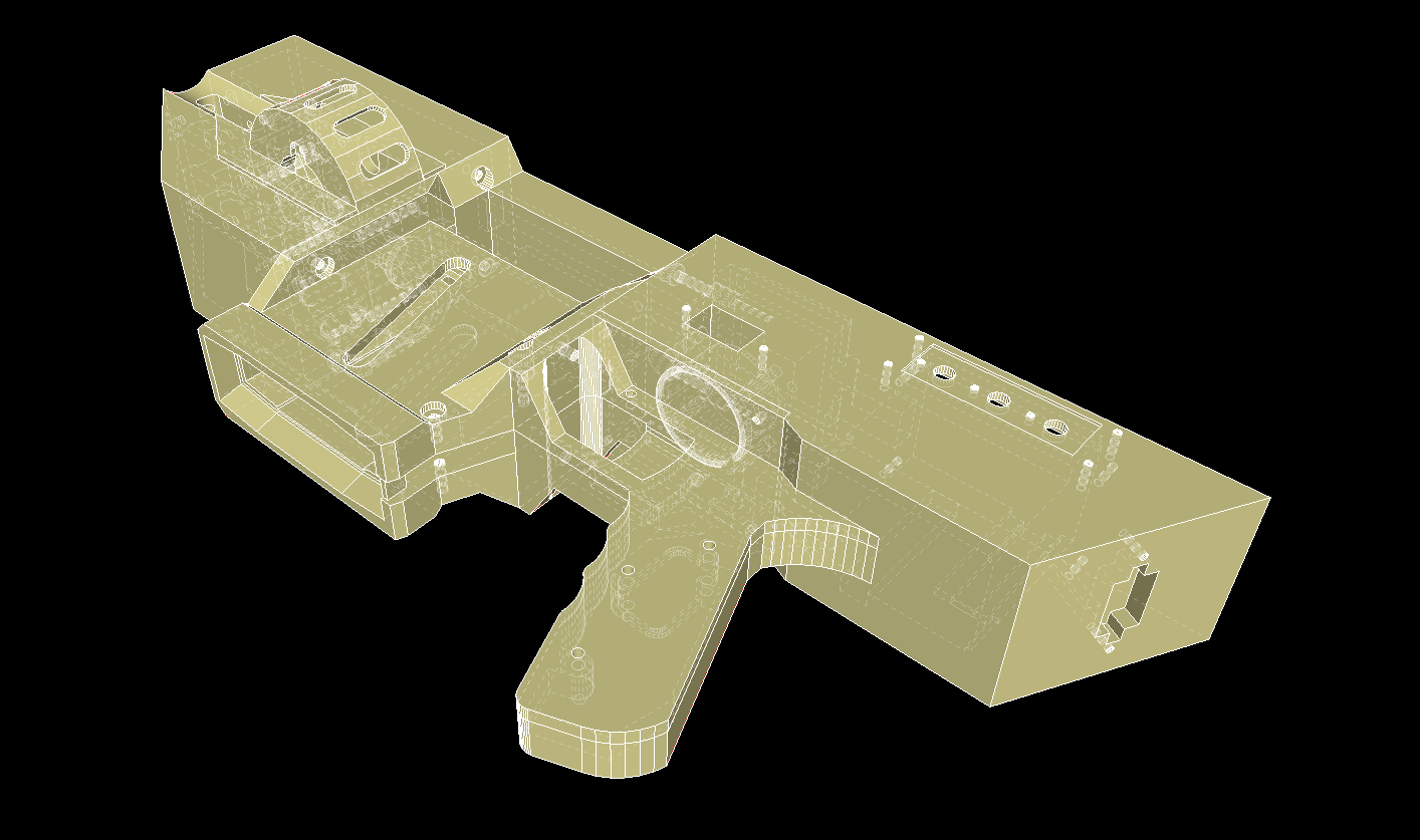
I soon realized that the blaster's signature front foregrip was, sadly, too small to fit in the ESC's. It could work if the Esc's used were smaller, but the ones I was currently using were big and chunky by comparison, so a different foregrip was needed to fit them. The result is pictured below. It is not quite as good looking as that original design, but it works and still looks decent at the same time.


The weapon looks pretty neat in a digital rendering, but how about real life? Would it function as desired? That is what I next planned to find out.
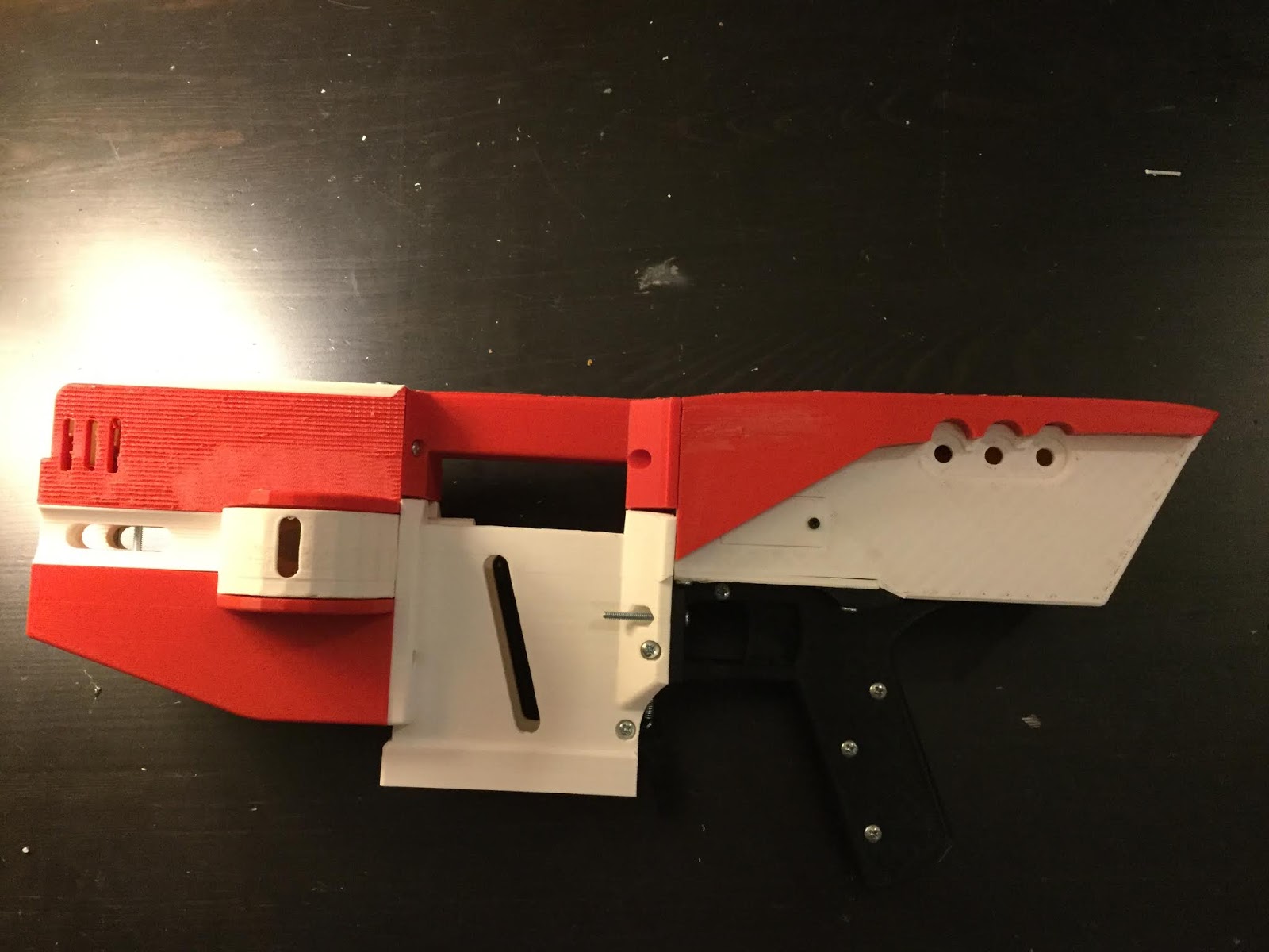
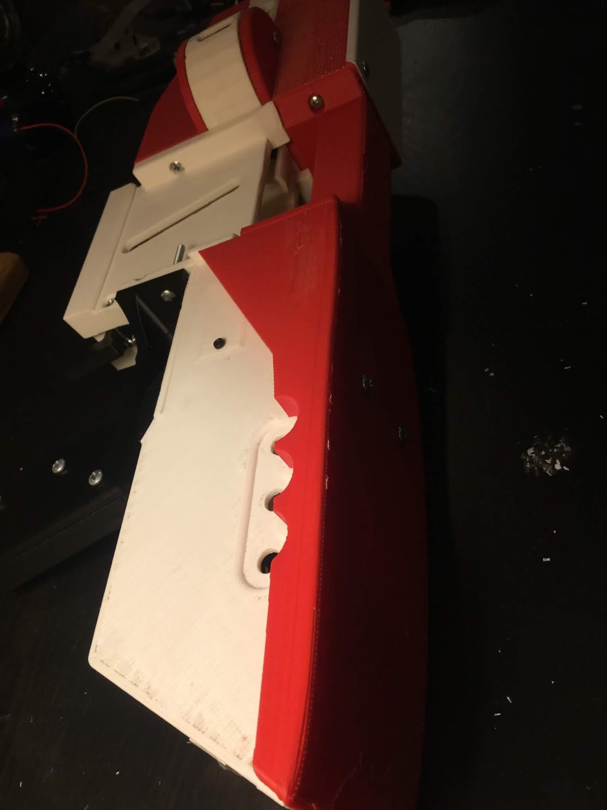
A little pretext here, (an excuse, if you will) I printed the entirety of the Mayor in ABS plastic, which, warps. Big time. Until the last few prints, I had used ABS slurry and masking tape to hold the plastics down. This lessened the warping, but did not rid me of it entirely. Many of the pieces you see here will be reprinted later, as I now have a nice PEI bed the holds prints like these firmly in place.
   On the plus side, things fit well in the blaster and worked accordingly. The next step was to put it together. The Mayor had several shortcomings when it comes to assembly. There are several locations (like where the screws hold on the trigger and the shroud) where the screws bore into, and get their hold from, plastic. This is not good at all. I spent quite some time thinking on how to combat this, and have only recently come up with the solution, so the weapon in the images below does not have these improvements (yet).


For the flywheel cage, I used and ideation similar to that of torukmakto4 and FDL-1 (as stated in a previous blog) when producing it. There is, however a major difference between those cages and the one I am currently using. They both have their motors screwed directly into the plastic. Unlike the mentioned people, I implemented some nice, metal motor brackets for the motors to be screwed into. Those, in turn, are then screwed into the cage with 4 larger, stronger screws. This creates a wider anchor range and is less likely to shear off due to normal wear and tear.
   The Mayor uses 2205 type brushless motors with 2300 KV rating. The flywheels, as mentioned in the original post are 9.5mm (crush space). This setup on 3s yields roughly 150 FPS, the same as a typical FDL blaster. (you see me making many references to FDL, and that is because it is the brushless standard in the nerfing community). The T19 yields 180 FPS, and that is because it runs on a 4s setup. If the Mayor were to also use a 4s LiPo, output would be roughly the same, as most other aspects (I.E motor type, etc.) are pretty similar across both platforms. The battery tray is plenty big enough for a 4s LiPo, so switching to a beefier battery is as simple as plugging one in.

   Unfortunately, while testing,  I had a mishap with a simonK firmware and it took out 2 of my ESCs and one motor with a fantastic bang. I, luckily have spare Esc's, but will need fresh motors to fully complete the weapon.

Current iteration files are on Thingiverse and source code will be up on GitHub soon.


Sunday, December 23, 2018

(WIP) G1 Prototype

That is the name for now since I cannot think of anything better. This is my foray into the growing number of fully-3D printed nerf blasters being produced by modders like me. So, let the blog begin!

This blaster initially stemmed from my original desire to create a brushless nerf blaster much like the FDL2. I originally decided to place the internals inside a rapidstrike shell because I did not want to waste time and filament to produce a blaster from scratch. I originally assembled this into a semi-decent package that worked to a degree. The issue came with the flywheel cage. The original cage I had used in this weapon was based on a 42mm OFP cage. It was designed to fit a set of 2212 brushless motors I had acquired earlier. The performance of these wheels were better than stock, but not by much. Several reddit questions later, and  I deducted that the cage I was currently using was not the best for the job, as the best type of cages were not stock-sized. I later found this article that reinforced what I was already thinking. The answer was clear: I needed a different cage. Using the research that had already been laid down before me by the fantastic efforts of people like torukmakto4 and FDL-1, I began to design a better system for my blaster. I quickly whipped out a prototype cage much like the one described in the above hy-con blog. It had an outer diameter of 50mm, and a complete envelopment of 9.5mm. Everything worked, and it laid the grounds for what I produced below.

Unlike the previous brushless weapons that were designed to be prototype test beds, I wanted something that actually looked good. Those others were great and all, but the research into weather brushless flywheelers will actually work has already been proven by said weapons, so why continue to make them look boxy and malshapen? I present to you the (work in progress) G1:

I’ll admit, it is not the most form pleasing in this current iteration, but that is OK. I am still developing its finer aesthetic details, but the basic form of the blaster is still present in this cad prototype.


For a test, I printed off this section of the blaster’s handle. It is cut down in every area that is not essential, but it shows the basic principle in which it works.

I will post more developments as they come.